
Injection Mold Design Review Checklist
author: CHEN
2025-05-19
In the process of injection mold design and manufacturing, a thorough design review is a critical step in ensuring product quality, mold durability, and production efficiency. A systematic and comprehensive evaluation at the early stages can effectively prevent potential issues and significantly enhance the overall performance of the mold.
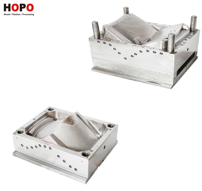
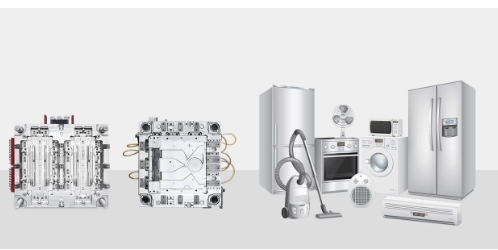
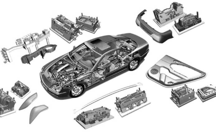
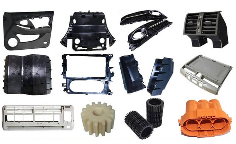
With over 13 years of experience in the industry, HOPO MOULD specializes in the design and manufacture of high-precision injection molds for automotive applications — including front grilles, headlight molds — as well as home appliance molds such as washing machine components.
Leveraging advanced design techniques, rich structural experience, an innovative automatic cutting system, and superior surface treatment capabilities, we are committed to delivering reliable, long-lasting mold solutions tailored to our clients' needs. This checklist is designed to support design teams in conducting effective evaluations, ensuring every mold meets both customer expectations and industry standards.
Injection Mold Design Review Checklist
Part Design Review
- ☐ Is the part designed for manufacturability (DFM)?
- ☐ Are there uniform wall thicknesses to minimize sink marks/warpage?
- ☐ Are draft angles appropriate (typically 1–2°) for easy ejection?
- ☐ Have undercuts been minimized or eliminated?
- ☐ Are sharp corners replaced with fillets to reduce stress concentrations?
- ☐ Are tolerances clearly defined — and realistic?
Mold Layout & Cavity Design
- ☐ Is the number of cavities appropriate for production volume?
- ☐ Is the part orientation within the mold optimized for filling and cooling?
- ☐ Are multi-cavity or family mold layouts balanced for flow and cooling?
- ☐ Are shut-off surfaces well-designed to avoid flash?
Cooling System Design
- ☐ Are cooling lines optimally placed for even temperature distribution?
- ☐ Are baffles, bubblers, or spiral cooling needed in hot zones?
- ☐ Is the cooling channel size sufficient for flow and maintenance?
- ☐ Are quick-connects or standard fittings planned?
Ejection System
- ☐ Are ejector pins placed uniformly and away from critical features?
- ☐ Will the part eject without sticking, warping, or distortion?
- ☐ Are sleeves, lifters, or stripper plates required for complex shapes?
- ☐ Is ejection balanced and timed appropriately?
Runner and Gate Design
- ☐ Is the runner system type appropriate (cold runner vs. hot runner)?
- ☐ Is the gate location ideal for uniform filling and minimizing weld lines?
- ☐ Is the gate type (edge, fan, submarine, etc.) suited to the part’s geometry?
- ☐ Are flow paths balanced to prevent short shots or overpacking?
Material Selection for the Mold
- ☐ Is the mold base material appropriate for expected production volume?
- ☐ Are cavities and cores made from the right steel or alloy (P20, H13, etc.)?
- ☐ Is the material hardened or treated to prevent wear and corrosion?
- ☐ Is coating (e.g., nitriding, chrome plating) needed for better life?
Mold Components & Standardization
- ☐ Are standard mold components (DME, HASCO, etc.) used where possible?
- ☐ Are replaceable inserts used in wear-prone areas?
- ☐ Are sliders, lifters, cams, or other actions used only where necessary?
- ☐ Are venting channels properly placed to avoid air traps?
Maintenance and Repair Accessibility
- ☐ Can critical inserts or wear parts be easily replaced?
- ☐ Are alignment features and pins properly located?
- ☐ Are all components accessible without major teardown?
- ☐ Are wear-prone components protected or overbuilt?
Mold Flow and Simulation
- ☐ Has mold flow analysis been completed?
- ☐ Are potential weld lines, air traps, and sink zones identified?
- ☐ Has warpage been simulated and addressed?
- ☐ Are packing, holding pressure, and fill times optimized?
Documentation and Communication
- ☐ Are 2D and 3D CAD files provided with revision control?
- ☐ Is a BOM (bill of materials) for mold components included?
- ☐ Is a maintenance guide or tooling manual available?
- ☐ Are tolerances, materials, and finishes clearly labeled?
Final Decision Points
- ☐ Is the design scalable if production ramps up?
- ☐ Does the mold meet ROI requirements for cost per part?
- ☐ Is there a clear plan for mold testing (T0/T1 runs)?
- ☐ Are timelines for DFM, steel cutting, sampling, and final approval realistic?
Selecting the right type of steel for SIM is essential for producing durable and high-quality parts.
The choice depends on the application and the required properties of the final product.
- Carbon Steel: Ideal for parts that need strength but don’t require corrosion resistance.
- Stainless Steel: Best for parts that need to withstand harsh environments, such as medical devices and automotive applications, thanks to its resistance to corrosion.
- Alloy Steels: Used when additional properties such as wear resistance or hardness are needed in specific parts.
The steel selection will depend on the functional requirements of your parts and the conditions they’ll be exposed to in their intended applications.
A rigorous design review process plays a vital role in minimizing costly revisions, improving production efficiency, and ensuring consistent mold quality. At HOPO MOULD , innovation and technical excellence remain at the core of everything we do. With a strong focus on automotive and appliance mold manufacturing, we continue to refine our expertise and elevate our standards to meet the evolving demands of the global market. We believe that a structured and disciplined approach to mold design not only enhances product reliability but also builds lasting trust with our clients. It is our hope that this checklist will serve as a valuable tool for engineers and designers, supporting them in achieving higher accuracy and efficiency — and helping them grow alongside HOPO MOULD toward a more precise and productive future in mold manufacturing.
FAQ About Mold Cooling Time
Q1: Can I use a standard cooling time for every part?
A: Not at all. Cooling time depends heavily on the material type, wall thickness, and mold design. For example, a thin-walled HDPE container may cool in just a few seconds, while a thick ABS component could take over 10 seconds. Relying on a “one-size-fits-all” time can lead to defects or wasted cycle time.
Q2: Is it true that reducing cooling time always improves productivity?
A: While shorter cycles sound good, it’s not always better. If you eject the part too early, warping, sink marks, or even part cracking can occur. The goal is optimized, not minimal cooling time—where the part is structurally stable without wasting seconds.
Q3: How does mold material impact cooling time?
A: Materials like aluminum dissipate heat faster than steel, which can cut cooling time by 20–40% in some applications. But they wear out faster in high-volume runs. Choosing the right mold base is about balancing cooling efficiency with durability and cost.
Q4: Can cooling channels be redesigned to reduce cooling time?
A: Yes. Smart cooling design—like conformal cooling, baffles, or bubblers—can dramatically improve heat extraction, especially in complex parts. Investing in better cooling channel design often delivers quick ROI through faster cycles.
Q5: What’s the impact of inconsistent wall thickness on cooling?
A: Uneven wall thickness leads to uneven cooling, which causes internal stress and visual defects like sink marks or warpage. Try to keep wall thickness consistent and avoid abrupt transitions whenever possible.
Q6: How accurate are cooling time formulas?
A: Basic formulas provide solid estimates—but they can’t account for all real-world complexities. For high-precision work, use simulation tools like Moldflow or Moldex3D to simulate cooling across the whole part geometry.
Q7: Can increasing coolant flow rate always speed up cooling?
A: To a degree. Once your system achieves turbulent flow, boosting flow rate has diminishing returns. It’s more effective to ensure good channel placement and coolant temperature control than to simply turn up the pump.
Q8: What’s the safe ejection temperature for most parts?
A: It varies. For example, ABS may eject safely around 100°C, while polypropylene can often be ejected at 80–90°C. If you go too low, cycle time is wasted; too high, and you risk part deformation. Always refer to material data sheets or test it in small batches.
Q9: How do I know if my cooling time is too long?
A: If your parts are solid and defect-free, but your overall cycle time is noticeably longer than industry benchmarks for the same part type and material, your cooling time is likely excessive. Try reducing it by 5–10% and monitor part quality.
Q10: Can part design alone help reduce cooling time?
A: Absolutely. Features like ribs instead of solid blocks, hollow structures, or uniform wall thickness all reduce cooling demands. Good part design can often shave seconds off the cycle without expensive changes to tooling.
Related Articles
 The Top Injection Molding Industry Leader 2026-02-24 0
 2026 Injection Molding Industry Leader 2026-02-24 0
 USA Top Custom Moulding Experts 2026-02-11 0
 2026 Architectural and Decorative Moulding Leaders in USA 2026-02-11 0
 2026 Top Industrial Plastic Injection Moulding Titans 2026-02-02 0
- 2026 Top Moulding Company 2026-02-02 0
- What Is an Aluminum Injection Mold and Why Is It Used 2026-01-19 0
 How Does Aluminum Material Grade Impact Mold Cost 2026-01-19 0
 The Cost of an Aluminum Injection Mold 2026-01-19 0
 What Affects the Cost of an Aluminum Injection Mold 2026-01-19 0
 What Is the Strength of the 7 Most Common Injection Molding Plastics 2026-01-12 0
 How Thick Can You Injection Mold Plastic 2026-01-12 0
 What Are the 7 Steps of PLC 2025-12-16 0
 What Is PLC in Injection Molding 2025-12-16 0
- What Is the Minimum Wall Thickness of the 7 Main Types of Plastic 2025-12-11 0
 Industry Standards or Guidelines for Wall Thickness by Application 2025-12-11 0
 Why Does Plastic Shrink More in Thick Sections in Injection Molding 2025-12-02 0
 The Strongest Plastic for Injection Molding 2025-12-02 0
- Why is Machine Assistance Essential in High-Demand Mould Shops 2025-11-20 0
 Common Defects and Limitations Must Mold Finishers Anticipate with CP 2025-11-20 0
