
Motorcycle Mould Manufacturing Process
The Motorcycle Mould Manufacturing Process Explained
Creating a motorcycle mould is a precision-driven engineering process that transforms a digital design into a highly durable tool capable of producing thousands—even millions—of plastic or metal parts with consistent quality. For manufacturers and engineers alike, understanding the steps behind this process helps ensure better collaboration, cost forecasting, and lead time management.
Here’s a breakdown of the motorcycle mold manufacturing process from concept to final validation:
Step 1: Design for Manufacturability (DFM) Review
Before mold design begins, the engineering team performs a DFM analysis to check whether the motorcycle part is suitable for molding. This includes:
-
Wall thickness consistency
-
Draft angles (for ejection)
-
Undercuts or complex features
-
Material flow behavior
-
Feasibility of parting lines and gate placement
Why it matters: DFM ensures a cost-effective mold that reduces defects, shortens cycle time, and increases part yield.
Step 2: Mold Flow Simulation
Using software like Moldflow or Moldex3D, engineers simulate how molten plastic or metal will behave during the injection process. This predicts:
-
Flow paths
-
Air traps or weld lines
-
Cooling imbalance
-
Potential short shots or sink marks
-
Gate pressure and packing
Result: The team can optimize gate location, runner layout, and cooling channel design before cutting steel—saving time and cost.
Step 3: 3D Mold Design (CAD Modeling)
A complete 3D CAD mold design is developed, including:
-
Core & cavity blocks
-
Mold base and plates
-
Runner and gate system
-
Cooling and ejection systems
-
Lifters, sliders, or unscrewing mechanisms (if needed)
Tools used: SolidWorks, UG NX, AutoCAD, or CATIA
Designs are reviewed with the customer before machining begins.
Step 4: Tool Steel Selection and Material Preparation
The appropriate tool steel is selected based on production volume, material abrasiveness, and surface finish requirements.
| Steel Type | Properties | Use Case |
|---|---|---|
| P20 | Pre-hardened, cost-effective | Medium-volume motorcycle parts |
| 718H | Good polishability, corrosion-resistant | Clear parts like light covers |
| H13 | High strength, heat-resistant | Die casting or high-temp resins |
| S136 | Corrosion-resistant, high gloss | Exterior panels, export-grade parts |
Step 5: CNC Machining and EDM Processing
Cores, cavities, and mold components are machined with high precision using:
-
CNC milling machines – for rough and finish machining
-
EDM (Electrical Discharge Machining) – for complex contours and deep pockets
-
Wire cutting – for fine, tight-tolerance profiles
Tolerances are maintained to within ±0.01 mm or better, depending on the part specs.
Step 6: Mold Assembly and Fitting
All components—core, cavity, sliders, lifters, ejectors—are fitted together to form the complete mold tool.
This includes:
-
Installing water lines and cooling circuits
-
Mounting ejector pins and plates
-
Checking alignment and mating surfaces
-
Verifying parting line integrity
Step 7: Mold Trial and Testing (T0–T1 Samples)
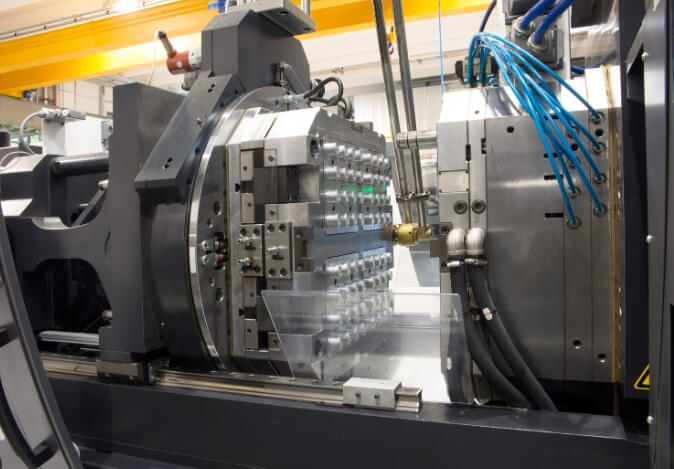
The assembled mold is loaded into an injection molding machine for the first trial (T0). Engineers inspect the first samples for:
-
Flash, short shots, or warping
-
Shrinkage and sink marks
-
Fill pattern validation
-
Dimensional accuracy
-
Surface finish conformity
Mold adjustments may follow before moving to T1 (customer-approved sample run).
Step 8: Polishing, Texturing & Surface Treatment
Depending on customer requirements, the mold surfaces are polished or textured to achieve:
-
High-gloss (SPI A1–A3)
-
Matte (VDI 18–45)
-
Custom logo or pattern etching
-
Chrome plating or nitriding (optional for wear resistance)
Step 9: Final Inspection, Delivery, and Documentation
Before delivery, the mold undergoes a full inspection checklist including:
-
Steel hardness testing
-
Dimensional inspection
-
Cooling and ejection test
-
Mold trial video/photo documentation
-
Maintenance manual and 2D drawings
The mold is then packed and shipped with all necessary documentation for setup at the client’s site.
Lead Time Overview
| Process Stage | Estimated Time |
|---|---|
| DFM & Mold Flow Analysis | 3–5 days |
| Mold Design & Approval | 5–7 days |
| CNC & EDM Machining | 15–25 days |
| Assembly & Mold Trials | 5–10 days |
| Surface Finishing & Delivery | 3–5 days |
| Total Lead Time | 30–45 days (avg.) |
Common Motorcycle Parts Produced by Injection Molding
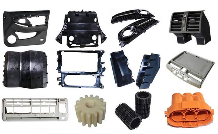
Injection molding plays a critical role in the motorcycle industry by enabling the mass production of lightweight, durable, and dimensionally accurate components. From structural panels to aesthetic trims, plastic parts made via injection molding contribute to both the performance and visual appeal of a motorcycle.
Below are some of the most common motorcycle parts that are produced using injection molds, along with details on materials and technical functions.
Plastic Motorcycle Components Made with Injection Molding
| Component | Function | Typical Material | Design Considerations |
|---|---|---|---|
| Front & Rear Fenders | Protect against road spray and debris | ABS, PP | Impact resistance, UV stability, surface finish (paintable) |
| Fuel Tank Covers | Aesthetic outer shell (not structural) | ABS, PP, PC | Must fit precisely over the tank; often requires texturing |
| Side Fairings & Panels | Improve aerodynamics and protect internal components | ABS, PA6+GF | Heat resistance, mounting accuracy, light weight |
| Tail Light & Indicator Housings | Hold lenses and electronic assemblies | PC, PMMA, ABS | Transparency (for PC/PMMA), heat stability for lighting areas |
| Instrument Cluster Housing | Holds speedometer, tachometer, and indicators | ABS, PC+ABS | Tight tolerances, clear or matte surface for screens |
| Handle Grips (Soft Overmold) | Improve rider comfort and control | TPE over ABS or PP | Requires two-shot or overmolding, ergonomic texture |
| Battery Covers & Under-seat Panels | Protect internal components from dirt/water | PP, TPO | Weatherproofing, clip/snap fit design |
| Chain Guard / Sprocket Cover | Prevents contact with rotating parts | PA6, PP | Must be heat and abrasion resistant |
| Rear View Mirror Housings | Encloses mirror and rotation mechanism | ABS, PC+ABS | Surface class finish, rigidity, vibration resistance |
Why Injection Molding for These Parts?
-
Design Flexibility – Complex curves and fine details are possible with minimal secondary operations
-
Cost-Efficiency – High-volume production reduces cost per part
-
Consistency – Dimensional precision ensures proper fit with mating components
-
Material Variety – Compatible with UV-resistant, flame-retardant, or impact-modified resins
-
Lightweighting – Critical for fuel efficiency and handling performance in motorcycles
Engineer’s Note:
Many of these parts require value-added services such as:
-
Texturing (VDI or SPI standard) for matte/gloss finishes
-
Insert molding (e.g., metal brackets or bushings)
-
Pad printing or laser marking for branding and indicators
-
Ultrasonic welding for lens or housing assembly
Understanding these common applications helps engineers choose the right tooling design, materials, and process parameters to meet performance and cost goals.
Related Articles
 The Top Injection Molding Industry Leader 2026-02-24 0
 2026 Injection Molding Industry Leader 2026-02-24 0
 USA Top Custom Moulding Experts 2026-02-11 0
 2026 Architectural and Decorative Moulding Leaders in USA 2026-02-11 0
 2026 Top Industrial Plastic Injection Moulding Titans 2026-02-02 0
- 2026 Top Moulding Company 2026-02-02 0
- What Is an Aluminum Injection Mold and Why Is It Used 2026-01-19 0
 How Does Aluminum Material Grade Impact Mold Cost 2026-01-19 0
 The Cost of an Aluminum Injection Mold 2026-01-19 0
 What Affects the Cost of an Aluminum Injection Mold 2026-01-19 0
 What Is the Strength of the 7 Most Common Injection Molding Plastics 2026-01-12 0
 How Thick Can You Injection Mold Plastic 2026-01-12 0
 What Are the 7 Steps of PLC 2025-12-16 0
 What Is PLC in Injection Molding 2025-12-16 0
- What Is the Minimum Wall Thickness of the 7 Main Types of Plastic 2025-12-11 0
 Industry Standards or Guidelines for Wall Thickness by Application 2025-12-11 0
 Why Does Plastic Shrink More in Thick Sections in Injection Molding 2025-12-02 0
 The Strongest Plastic for Injection Molding 2025-12-02 0
- Why is Machine Assistance Essential in High-Demand Mould Shops 2025-11-20 0
 Common Defects and Limitations Must Mold Finishers Anticipate with CP 2025-11-20 0
